- 型号 & 关键词搜索
- 交叉搜索
- 参数搜索
- 库存查询与购买
This webpage doesn't work with Internet Explorer. Please use the latest version of Google Chrome, Microsoft Edge, Mozilla Firefox or Safari.
请输入3个以上字符 Search for multiple part numbers fromhere.
The information presented in this cross reference is based on TOSHIBA's selection criteria and should be treated as a suggestion only. Please carefully review the latest versions of all relevant information on the TOSHIBA products, including without limitation data sheets and validate all operating parameters of the TOSHIBA products to ensure that the suggested TOSHIBA products are truly compatible with your design and application.Please note that this cross reference is based on TOSHIBA's estimate of compatibility with other manufacturers' products, based on other manufacturers' published data, at the time the data was collected.TOSHIBA is not responsible for any incorrect or incomplete information. Information is subject to change at any time without notice.
请输入3个以上字符
How accurate is the detected temperature?
Depending on the combination of Thermoflagger™ and the PTC thermistor used , there may be variations in the detected temperature.
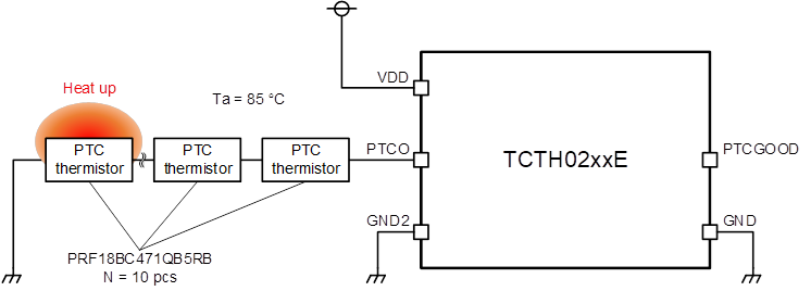
For reference, Table-1 shows the simulation results of the overheat detection temperature using the TCTH02xxE and Murata Manufacturing's PTC thermistor (POSISTOR), PRF18BC471QB5RB.
| Ambient temperature (Ta) | ||||||||||
|---|---|---|---|---|---|---|---|---|---|---|
| 25ºC | 50ºC | 85ºC | ||||||||
| Min | Typ. | Max | Min | Typ. | Max | Min | Typ. | Max | ||
| Conected PTC thermistor quantity (pcs) |
1 | 111ºC | 120ºC | 131ºC | 110ºC | 120ºC | 134ºC | 110ºC | 120ºC | 134ºC |
| 5 | 111ºC | 120ºC | 131ºC | 110ºC | 120ºC | 133ºC | 109ºC | 120ºC | 134ºC | |
| 10 | 110ºC | 120ºC | 131ºC | 109ºC | 120ºC | 133ºC | 107ºC | 119ºC | 133ºC | |
| 15 | 110ºC | 119ºC | 131ºC | 108ºC | 119ºC | 133ºC | 104ºC | 118ºC | 133ºC | |

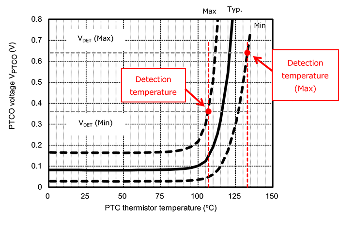
The variation in the detection temperature depends on VDET, IPTCO variation of Thermoflagger™, the resistance variation of the PTC thermistor, the number of connected PTC thermistors, and the ambient temperature. Before using this device, it is recommended to thoroughly verify it in an actual operating environment.

As an example, the following shows a simulated result when TCTH02xxE and PRF18BC471QB5RB 10 are combined at ambient (Ta) of 85°C. The combined temperature is 119ºC with a tolerance +14ºC/-12ºC.

For more information, refer to the application notebook, " Circuit proposal using Thermoflagger™ TCTH0 series and PTC thermistors ".
Related Links
The following documents also contain related information.


