- 型号 & 关键词搜索
- 交叉搜索
- 参数搜索
- 库存查询与购买
This webpage doesn't work with Internet Explorer. Please use the latest version of Google Chrome, Microsoft Edge, Mozilla Firefox or Safari.
请输入3个以上字符 Search for multiple part numbers fromhere.
The information presented in this cross reference is based on TOSHIBA's selection criteria and should be treated as a suggestion only. Please carefully review the latest versions of all relevant information on the TOSHIBA products, including without limitation data sheets and validate all operating parameters of the TOSHIBA products to ensure that the suggested TOSHIBA products are truly compatible with your design and application.Please note that this cross reference is based on TOSHIBA's estimate of compatibility with other manufacturers' products, based on other manufacturers' published data, at the time the data was collected.TOSHIBA is not responsible for any incorrect or incomplete information. Information is subject to change at any time without notice.
请输入3个以上字符
请说明IGBT的电压谐振软开关操作。

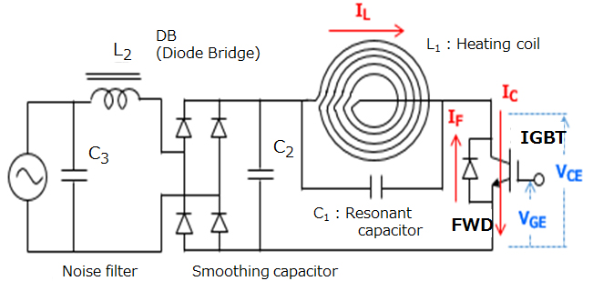
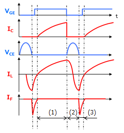
图(a)显示了作为软开关应用示例的电压谐振电磁炉的示意图。图(b)显示了其操作和波形。
在图(a)的电路中,当IGBT导通时,电流流过加热线圈(L1)。当IGBT关断时,L1和C1进入谐振状态,从而向IGBT施加正弦电压。L1和C1之间的谐振方向转向,导致C1电压抵消C2电压。当C1电压超过C2电压时,电流开始流过C1-C2-FWD-C1回路。在此期间,IGBT的集电极-发射极电压等于续流二极管(FWD)的正向电压(VF),几乎为零。此时,IGBT重新导通。最后,电流再次从输入侧流过加热线圈(L1)。重复此顺序。
电压谐振电路价廉物美,因为它不需要很多组件。然而,当系统需要高功率时,需通过耐压强度非常高的IGBT来处理高谐振电压。因此,在许多感应式家用电器(功率:100V交流时高达1.5kW;200V交流时高达3kW)中使用了电压谐振电路。输入侧的滤波电容器(C2)的电容较低,因为它在单个脉冲周期内接收电力。C2两端的电压具有全正弦波形,从而导致输入侧的功率因数较高。因此,使用电压谐振电路无需功率因数校正(PFC)电路。

- IGBT导通。
集电极电流流经L1。 - IGBT关断。
L1和C1进入谐振状态,导致电压升高。 - FWD传导。
存储在C1中的能量通过FWD流回电源。当谐振电压降至参考电压以下时,向IGBT输入“on”(导通)信号。
重复步骤1至3。

