- 型号 & 关键词搜索
- 交叉搜索
- 参数搜索
- 库存查询与购买
This webpage doesn't work with Internet Explorer. Please use the latest version of Google Chrome, Microsoft Edge, Mozilla Firefox or Safari.
请输入3个以上字符 Search for multiple part numbers fromhere.
The information presented in this cross reference is based on TOSHIBA's selection criteria and should be treated as a suggestion only. Please carefully review the latest versions of all relevant information on the TOSHIBA products, including without limitation data sheets and validate all operating parameters of the TOSHIBA products to ensure that the suggested TOSHIBA products are truly compatible with your design and application.Please note that this cross reference is based on TOSHIBA's estimate of compatibility with other manufacturers' products, based on other manufacturers' published data, at the time the data was collected.TOSHIBA is not responsible for any incorrect or incomplete information. Information is subject to change at any time without notice.
请输入3个以上字符
CMOS逻辑IC 04(反相器)和U04(无缓冲反相器)有什么区别?
作为标准功能CMOS逻辑IC的反相器,有“04”和“U04”两种。“04”用于一般逻辑处理(数字信号处理),“U04”主要用于晶振电路、RC振荡电路等振荡器。

- 04:具有3级反相器结构,第一级针对输入进行优化,最后一级具有缓冲器功能。
- U04:由单个反相器级组成,具有输入级和输出级(缓冲级)。
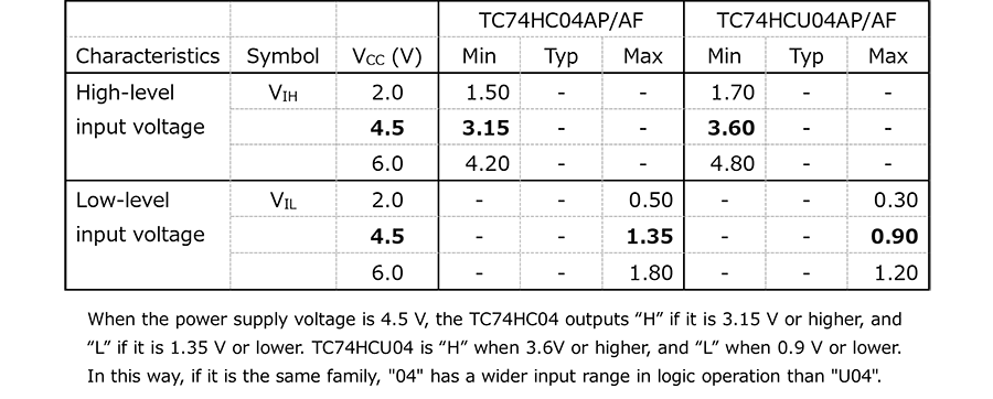
“04”和“U04”的结构如图1所示。“04”针对输入块和输出所需性能优化了MOS尺寸。因此,在同一组(系列)中,“04”的输入电容小于“U04”的输入电容。“04”由于其3级结构而具有高增益。此外,用于判断“H”和“L”的高电平/低电平输入电压范围(VIL、VIH)比“U04”更宽(表1),并且噪声容限较高。然而,传输延迟时间稍长一些。


图2显示了使用反相器的振荡器电路的概念图。
上电时的噪声等干扰成为振荡来源并进入输入端Vin。这些来源非常小,以致会在逆变器的线性区域内被放大,在反馈电路中经过滤波并计入输入端。振荡条件包括反馈信号的相位与输入信号同相,并且逆变器的增益大(“输入”+“反馈信号”的幅值大于原始输入信号)。
“04”的输入电容小,因此具有宽频带和高增益。其可达到比“U04”更高的振荡频率。仅考虑这一点,“04”似乎比“U04”更适用于振荡应用环境。然而,用于振荡的线性区域在表1所示的区域之外(例如,在4.5 V条件下,“04”为1.35 V至3.15 V,“U04”为0.90 V至3.6 V),因此“U04”的范围更宽泛。振荡信号必须在此范围内循环才能稳定振荡。考虑到在目标频率下的更稳定振荡要求,建议在振荡电路中使用“U04”。
相关链接
以下文档也包含了相关信息。
关于反相器电路和振荡信息,请参考以下e-Learning内容。
e-Learning:
关于通用逻辑基础知识,请参考以下文档。
应用说明:
请参考我们的推荐产品。


