


- 型号 & 关键词搜索
- 交叉搜索
- 参数搜索
- 库存查询与购买
This webpage doesn't work with Internet Explorer. Please use the latest version of Google Chrome, Microsoft Edge, Mozilla Firefox or Safari.
请输入3个以上字符 Search for multiple part numbers fromhere.
The information presented in this cross reference is based on TOSHIBA's selection criteria and should be treated as a suggestion only. Please carefully review the latest versions of all relevant information on the TOSHIBA products, including without limitation data sheets and validate all operating parameters of the TOSHIBA products to ensure that the suggested TOSHIBA products are truly compatible with your design and application.Please note that this cross reference is based on TOSHIBA's estimate of compatibility with other manufacturers' products, based on other manufacturers' published data, at the time the data was collected.TOSHIBA is not responsible for any incorrect or incomplete information. Information is subject to change at any time without notice.
请输入3个以上字符
如何计算散热器的热阻?
介绍音频功率IC的散热设计。
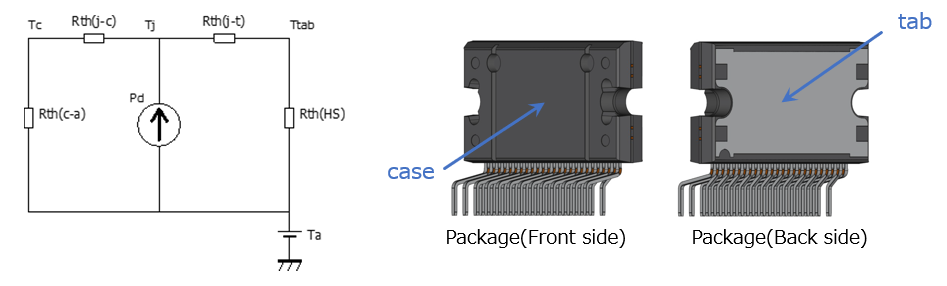
图1显示了热模型以及封装中各部分的名称。每个符号的涵义如下。
Pd:IC的功耗
Ta:工作环境温度
T:结温
Tc:外壳温度
Ttab:tab温度(音频功率IC散热器的温度)
Rth(j-c):结与外壳之间的热阻
Rth(j-t):结与tab之间的热阻
Rth(c-a):外壳与环境之间的热阻
Rth(HS):散热器(外部散热器)的热阻
本节将详细介绍如何得出外部散热器的尺寸,当HZIP25产品的每个通道的输出功率为4 W且Ta为40 ℃时,外部散热器的Rth(HS)(外部散热器的热阻)将使Tj小于150 ℃。
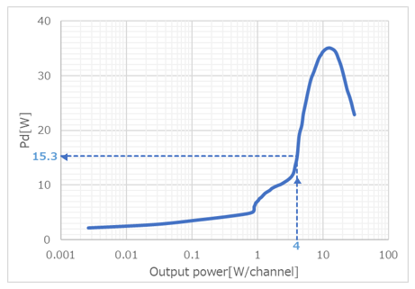
首先,从图2中读取每个通道输出功率为4W时的功耗。(Pd=15.3 W)
然后,使用下式计算出外部散热器热阻所需的Rth(HS)值。
如数据表所示,HZIP25封装的结与TAB之间的热阻Rth(j-t)为1.0 °C/W。
Tj > (Rth(j-t) + Rth(HS)) * Pd + Ta
150 > (1.0 + Rth(HS)) * 15.3 + 40
Rth(HS) < 4.88 ℃/W
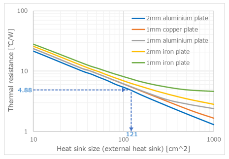
然后,利用图3读取外部散热器所需的尺寸。
根据估算,2 mm铝板需要121 cm^2及以上的面积。
每款产品的数据表中都有上述说明中使用的图2,可在散热器(外部散热器)制造商的网站上查阅图3。
相关链接
以下文档也包含相关信息。