- 型号 & 关键词搜索
- 交叉搜索
- 参数搜索
- 库存查询与购买
This webpage doesn't work with Internet Explorer. Please use the latest version of Google Chrome, Microsoft Edge, Mozilla Firefox or Safari.
请输入3个以上字符 Search for multiple part numbers fromhere.
The information presented in this cross reference is based on TOSHIBA's selection criteria and should be treated as a suggestion only. Please carefully review the latest versions of all relevant information on the TOSHIBA products, including without limitation data sheets and validate all operating parameters of the TOSHIBA products to ensure that the suggested TOSHIBA products are truly compatible with your design and application.Please note that this cross reference is based on TOSHIBA's estimate of compatibility with other manufacturers' products, based on other manufacturers' published data, at the time the data was collected.TOSHIBA is not responsible for any incorrect or incomplete information. Information is subject to change at any time without notice.
请输入3个以上字符
功率器件栅极驱动光耦中的有源米勒钳位(AMC)如何工作?
有源米勒钳位(AMC)可防止或减少功率器件因自导通而导致的误动作。
随着电机驱动和太阳能发电市场的扩大,对控制高压和大电流的逆变电路的需求也有望增长。逆变电路由三个半桥电路组成,这些半桥电路将IGBT或碳化硅功率MOSFET等功率器件串联在桥臂的高边和低边。由于碳化硅功率MOSFET的扩张和可使用低压功率器件的多电平逆变器的采用,对高频率驱动的需求正在增加。
当半桥高速开关时,米勒电容可导致栅极误导通(称为自导通)。关于自导通机制,详见东芝MOSFET应用说明“MOSFET自导通现象”,此处省略。但是,如果半桥电路中发生栅极误导通,由于上下桥臂瞬时短路,开关损耗增加,有可能导致功率器件因发热而损坏。
可采用以下方法防止自导通。
(1)在功率器件的栅极-源极或栅极-发射极之间增加电容
(2)使用有源米勒钳位电路
(3) 使用负偏置电压隔离电源,在关断期间将栅极电压降至负值,以免超过栅极阈值电压(Vth)。每种方法各有优缺点。增加电容的方法(1)无法提高半桥的开关速度。增设栅极负偏置电压隔离电源的方法(3)需要为负电压提供新的绝缘电源。在某些情况下,栅极电压无法强制降至负值。这取决于碳化硅功率MOSFET的特性。
下面从维持高速开关和简化功率器件的栅极隔离电源的角度介绍了有源米勒钳位方法(2)。
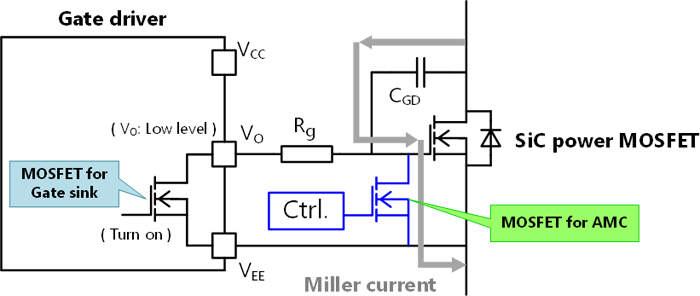
如图1所示,有源米勒钳位的作用就是在碳化硅功率MOSFET和IGBT等功率器件的栅极-源极或栅极-发射极之间增加一个N沟道MOSFET,从而在栅极关断期间使栅极-源极或栅极-发射极之间发生短路。增加的N沟道MOSFET可防止通过米勒电容的电流流过功率器件的栅极电阻(Rg),以抑制栅极电压的上升。这种方法可防止自导通。

东芝提供内置有源米勒钳位和内置短路保护功能的智能栅极驱动光耦TLP5222、TLP5212、TLP5214A,以及内置有源米勒钳位的单栅极驱动光耦TLP5814H。
本节介绍内置于TLP5814H的有源米勒钳位。
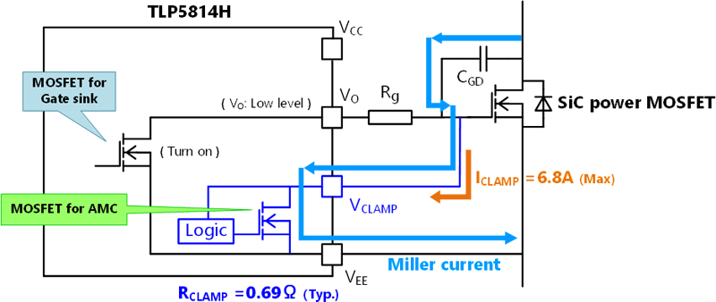
图2显示了TLP5814H的内部电路。

当满足以下两个条件并且功率器件的栅极-源极或栅极-发射极短路时,TLP5814H内置的有源米勒钳位就会发挥作用。
(1)其栅极输出电压(VO端子电压)很低。
(2)功率器件的栅极电压(VCLAMP)降至2.5 V以下。
图2所示的有源米勒钳位(AMC)内置MOSFET的导通电阻越低,AMC越有效。对于TLP5814H,AMC使用与栅极灌电流峰值为6.8 A的N沟道MOSFET等效的N沟道MOSFET,当VCLAMP=2.5 V时,导通电阻为0.69 Ω(典型值)。
TLP5814H适用于对栅极电压变化敏感的碳化硅功率MOSFET的栅极驱动。由于采用了业界标准的8引脚封装SO8L,因此也易于操作。TLP5814H在无法准备负偏置电压隔离电源的多电平逆变器中尤为有效,而此时栅极隔离电源可使功率器件使用数量增加一倍。
关于多电平逆变器的栅极正偏置电压隔离电源的详细信息,请参阅参考设计“采用MOSFET的3相多电平逆变器”。
相关链接
以下文件还包含相关信息。

