- 型号 & 关键词搜索
- 交叉搜索
- 参数搜索
- 库存查询与购买
This webpage doesn't work with Internet Explorer. Please use the latest version of Google Chrome, Microsoft Edge, Mozilla Firefox or Safari.
请输入3个以上字符 Search for multiple part numbers fromhere.
The information presented in this cross reference is based on TOSHIBA's selection criteria and should be treated as a suggestion only. Please carefully review the latest versions of all relevant information on the TOSHIBA products, including without limitation data sheets and validate all operating parameters of the TOSHIBA products to ensure that the suggested TOSHIBA products are truly compatible with your design and application.Please note that this cross reference is based on TOSHIBA's estimate of compatibility with other manufacturers' products, based on other manufacturers' published data, at the time the data was collected.TOSHIBA is not responsible for any incorrect or incomplete information. Information is subject to change at any time without notice.
请输入3个以上字符
Is the back of the SiC MOSFET package insulated?
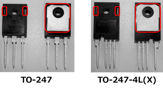
Figure 1 shows examples of Toshiba’s SiC MOSFET packages.
Toshiba’s SiC MOSFET's TO-247 and TO-247-4L(X) packages have exposed electrodes on the back when viewed from the marked side and are not insulated. The backside electrode is connected to the drain and has a high potential. When attaching a heat sink connected to the ground, insulate this electrode (indicated by the red frame in Figure 1) and make sure that it does not contact with peripheral components.
To calculate the creepage distance between the heat sink and the product or to determine the distance between the terminals, refer to MOSFET package information in the link below.
Package information:
● MOSFET
For attaching the heat sink, refer to the application notes in the link below.
● Thermal Design and Attachment of a Thermal Fin: Power MOSFET Application Notes (0.94MB)

Related links
The following documents also contain related information.


