


Developing Thermal Design Guidelines for Power MOSFETs in a Chassis
Detailed simulations of the thermal behavior of MOSFETs in a closed chassis allow the development of guidelines for improving system design for MOSFET placement in conjunction with the use of fans, grills, and heatsinks.
Introduction
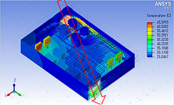
MOSFETs are ubiquitous in electronics, and their performance significantly impacts the thermal characteristics of a design. Physically evaluating that impact can be challenging, but it can be closely modeled using software tools from companies like Ansys to simulate thermal flow, as shown in Figure 1.
Chapter 1: Thermal Simulation conditions
It is difficult to develop evaluation boards that represent all possible thermal conditions due to time and cost constraints. Well-designed simulations, however, provide deep insight into the airflow and additional cooling accommodations. Such models are highly adaptable, allowing research into many different conditions, and do not involve the costs associated with evaluation boards.
This article will discuss the simulation modeling of the thermal behavior of MOSFETs in a closed chassis. We will investigate the impact of:
- Chassis type
- PCB size
- MOSFET placement and spacing
- Grill size
- Forced versus. convection cooling
- MOSFET and chassis heatsinks
The results of the simulations are presented, followed by design recommendations based on those findings.
Overview of the Two Different System Models
In this article, we will examine two different design models consisting of different chassis dimensions, PCB dimensions and construction, and with and without additional components.
Two Chassis Models
Two types of chassis models are used for the simulation:
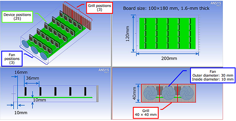
- Model 1 chassis is 120 × 200 × 40 mm, with all six sides of the chassis configured as heat insulators. This model is illustrated in Figure 2.
- Model 2 chassis is 140 × 200 × 40 mm, with 1mm thick aluminum plates on all six sides to facilitate chassis temperature analysis while also serving as a heat sink.
Two PCB Models
The PCB for Model 1 is 100 × 180 × 1.6 mm with four layers. The top, bottom, and inner layer trace thicknesses are all 35 μm.
The PCB for Model 2 is 125 × 175 × 1.6 mm with four layers. The top, bottom, and inner layer trace thicknesses for this model are 70, 70, and 35 μm, respectively.
Note that all PCB boards are made from FR4, and the copper percentage for the traces is set at 80 %. The boards do not have a solder resist layer on top, and the simulation settings include only emissivity to compensate for the effect of that layer. In addition, the boards do not have through-holes and thermal vias.
Components
The model for the MOSFETs is based on the TO-247 package with a chip size of 4 × 4 × 0.25 mm, a lead thickness of 0.6 mm, and a mold of 16 × 20 × 4.4 mm. To better optimize analysis time, MOSFETs are modeled using three parts—mold, chip, and lead—with the bonding wires and solder omitted. The result is a close approximation to a rectangular solid.
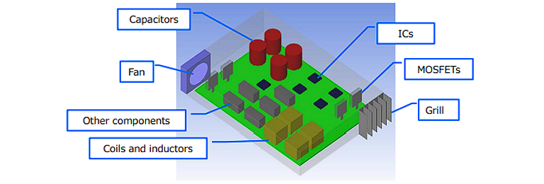
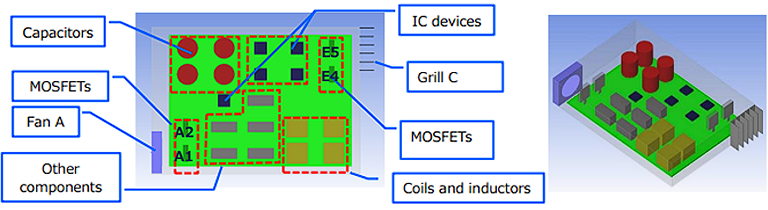
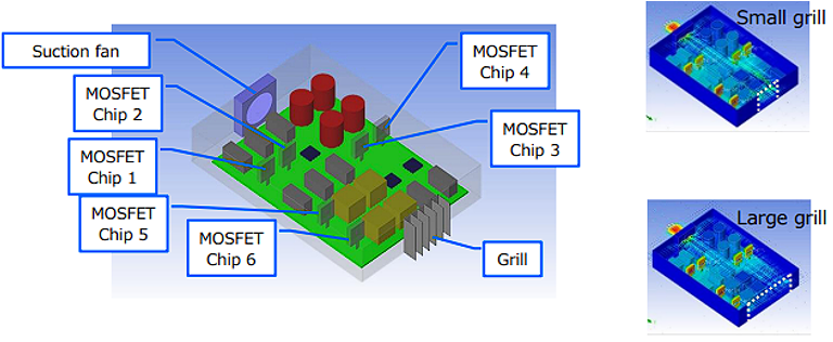
Model 2 also includes IC devices, inductors (i.e., coils and transformers), and electrolytic capacitors. The inductors and IC devices are modeled as resistance to airflow rather than heat-generating devices. A typical layout of this model is shown in Figure 3.
Fan and Grill
A 40 × 40 mm fan is used in the simulation, incorporating various P-Q (pressure-volume) curves for representation.
The grill, attached to the chassis wall, can be configured as either an inlet or outlet by using the fan as a suction or blower fan. Note that the grill has an opening ratio of 1.0.
Chapter 2: Evaluating Placement of a MOSFET
2-1: Evaluating Placement of a Single MOSFET
This simulation is the simplest case and uses Model 1 with a single MOSFET (2 W power dissipation) as the heat source. A solid understanding of the thermal behavior of a single MOSFET placed in various positions within the chassis, in conjunction with different fan and grill placements, serves as a starting point for the remaining simulations.
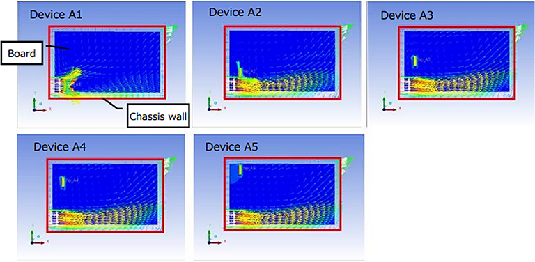
Figure 4 displays the various combinations of MOSFET, grill, and fan positions.
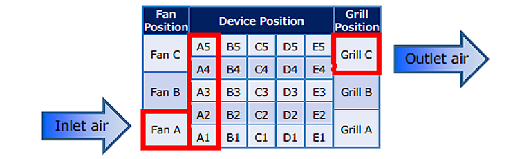
Airflow results obtained using Ansys software are shown in Figure 5 for device placements in A1, A2, A3, A4, and A5. Here, the fan is placed at position A and the grill at position C.
The MOSFET thermal resistance for this, and all remaining simulations, is calculated according to the following equation:
Thermal resistance = (average simulated chip temperature – ambient temperature) / power dissipation
According to the results for all possible combinations of device, grill, and fan placement, it becomes evident that positioning a MOSFET along the path directly leading from the fan to the grill is the most effective approach.
2-2: Evaluating Placement of 25 MOSFETs
Next, a total of 25 MOSFETs are placed in the model and simultaneously powered on, with the fan at the lower-left (fan position A) and grill at the upper-right corner (grill position C) of Model 1, respectively.
Similar to the single MOSFET simulation, the average MOSFET chip temperature is measured to calculate the MOSFET thermal resistance. A key variable in this simulation is the spacing between the MOSFETs.
As expected, the results shown in Figures 6 (closely spaced) and 7 (widely spaced) indicate that spacing is important for achieving the best thermal control. With wider spacing, the air moved more smoothly between the MOSFETs, causing MOSFET thermal resistance to decrease, regardless of whether a suction fan (left side of each image) or a blower fan (right side of each image) was used.
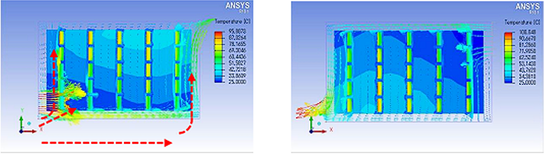
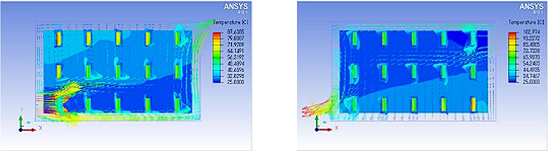
In both cases of closely and widely spaced MOSFETs, the suction fan does not perform as well as the blower fan.
Chapter 3: Thermal simulation for actual use
3-1: Thermal Simulation Using a More Realistic Model
Now we will simulate under more realistic conditions, as shown in Figure 8. Note the inclusion of additional ICs, coils, inductors, and other components. Also, recognize the fan and grill placements.
In this set of simulations, the fan and grill positions were again varied, and the thermal resistance of the MOSFETs was calculated. The results are provided in Table 1.
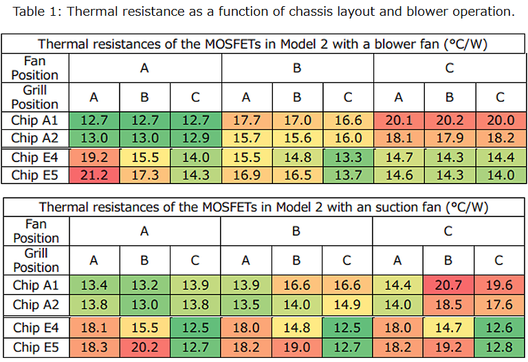
Fan position A with grill position C provided the best overall thermal performance for both modes of fan operation.
3-2: Effect of Grill Size on Thermal Performance
Using Model 2, the grill size effect was studied using a suction fan. The analysis provided data relating the grill size to the thermal resistance of six MOSFETs placed inside the chassis model shown at left in Figure 9. The results shown at the right of Figure 10 indicate that a larger grill more effectively cools the entire space within the chassis.
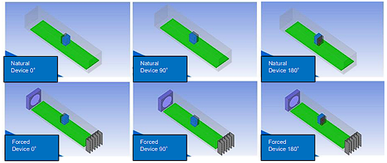
3-3: Natural Convection vs. Forced Convection
Forced convection pulls cool outside air into the chassis, while natural convection achieves cooling as the hot air from the heat sources rises, and cool air is pulled in to replace it. Note that natural convection requires an opening on the top instead of a grill. Natural convection is cheaper to implement because it does not require a fan; however, it is generally less effective in comparison.
The simulation setup and component placements are illustrated in Figure 10, where the left-hand image represents natural convection, and the right-hand image is forced convection.
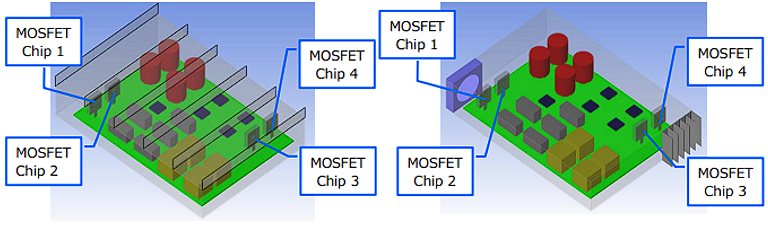
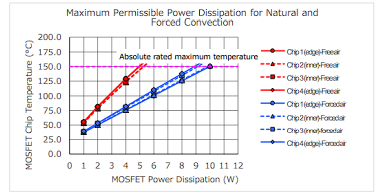
Figure 11 provides the results of these simulations. It is evident that forced convection provides better thermal performance with lower temperatures at all power levels. This serves as a reminder that fans, despite their associated cost, are a wise choice in thermal design.
Chapter 4: Effects of various heat dissipation measures
4-1: Impact of Chassis Width and MOSFET Distance From the Fan
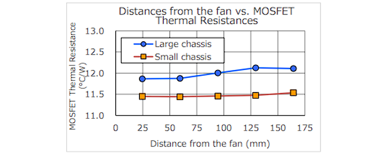
The next simulation focuses on studying the results of forced convection in relation to the width of the chassis. Figure 12 shows the two layouts implemented: one with a wide chassis and the other with a narrow chassis equal to the width of the fan.
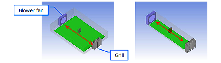
Both blow and suction fans are simulated, with their results summarized in Figure 13. For the small chassis, distance from the fan does not have as much impact as in the larger chassis, where airflow will not be as constrained.
4-2: Thermal Performance as a Function of Air Flow Volume
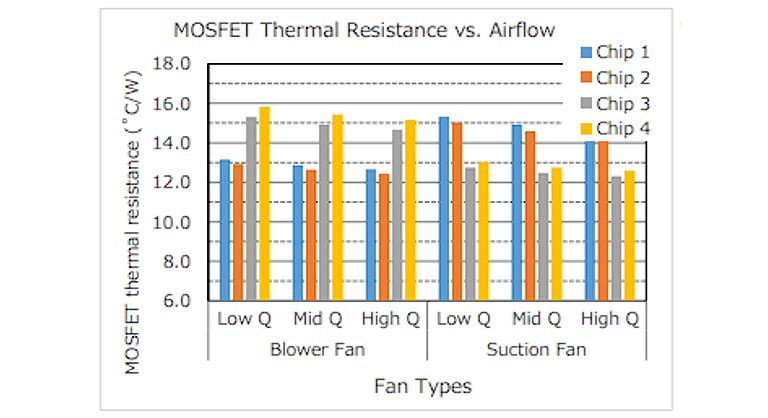
Fan performance has an effect on thermal design. Figure 14 illustrates a simulation layout for evaluating the impact of fan performance—using high, middle, and low Q (volumetric airflow) fans—on the thermal resistance of four MOSFETs.

Figure 15 summarizes the results of the simulation, and as expected, high-airflow fans achieve lower thermal resistance for all four chips. In the case of blower fans, the MOSFET closest to the fan experiences the lowest thermal resistance. For suction fans, the opposite holds true, with the MOSFET closest to the grill having the least thermal resistance. This intuitively makes sense since these MOSFETs are closest to the incoming cooler air.
4-3: Effect of MOSFET Heatsinks
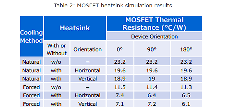
Another common approach to thermal design for MOSFETs involves using MOSFET heatsinks, which speed up heat dissipation by providing a larger surface area. Two different heatsink orientations are used: horizontal (with fins in the same plane as the PCB) and vertical. The six models evaluated are shown in Figure 16 with three different device and heat sink orientations crossed with the use of either natural or forced cooling methods.
The results are provided below in Table 2. For both natural and forced air cooling, the heatsink reduces the thermal resistance.
4-4: Chassis Heatsinks for Improved Cooling
Chassis heatsinks are another common approach in thermal design for power electronics. Since it can be difficult to attach heatsinks to individual MOSFETs when space is constrained, our final analysis examines the impact of using the chassis itself as a heatsink.
In this scenario, a Thermal Interface Material (TIM) is placed between the aluminum chassis and MOSFET to provide electrical insulation. The configuration and three approaches are shown in Figure 17: no heatsink, heatsinks attached to all four edge-placed MOSFETs, and chassis heatsinks for all four edge-placed MOSFETs.
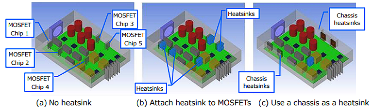
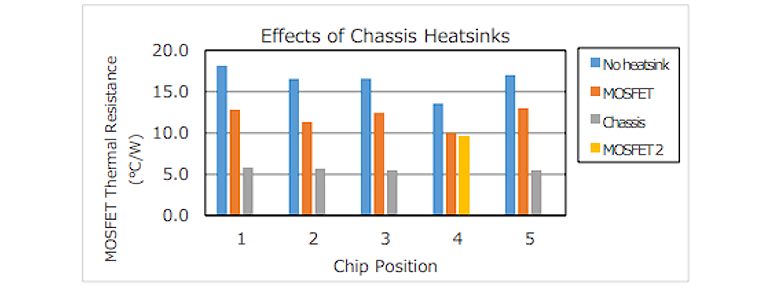
Figure 18 summarizes the results. Using a chassis as a heatsink is highly effective, but consideration will need to be given to the chassis material for obtaining comparable results.
Chapter 5: Summary and guidelines
Collecting all of the results described above, we can arrive at some general guidelines for system designs that employ MOSFETs:
- Forced convection is superior to natural convection because it generates a higher air velocity that leads to a greater cooling effect.
- High airflow fans, whether they are suction or blower fans, have a significant impact on average MOSFET thermal resistance.
- Blower fans are more effective in directly cooling hot devices, while suction fans work better in scenarios that require an entire board to be cooled.
- MOSFETs are more effectively cooled the closer they are to the fan.
- MOSFETs should be placed along the path between the fan and the grill and, wherever feasible, positioned close to the fan.
- Large components should not be placed directly in front of a fan because they compromise airflow throughout the chassis.
- A larger grill achieves better cooling results for the interior space as a whole.
- When MOSFET heatsinks are used, they work best when directly exposed to air, and in terms of configuration, the greatest area must be exposed to the airflow between the fan and grill.
- Chassis heatsinks are most effective when MOSFETs are placed along the sides of the chassis, assuming the chassis material has good thermal characteristics.
Related Content
If you are interested in thermal design, you may also like
Download PDF
Please click the button to download the PDF file.