
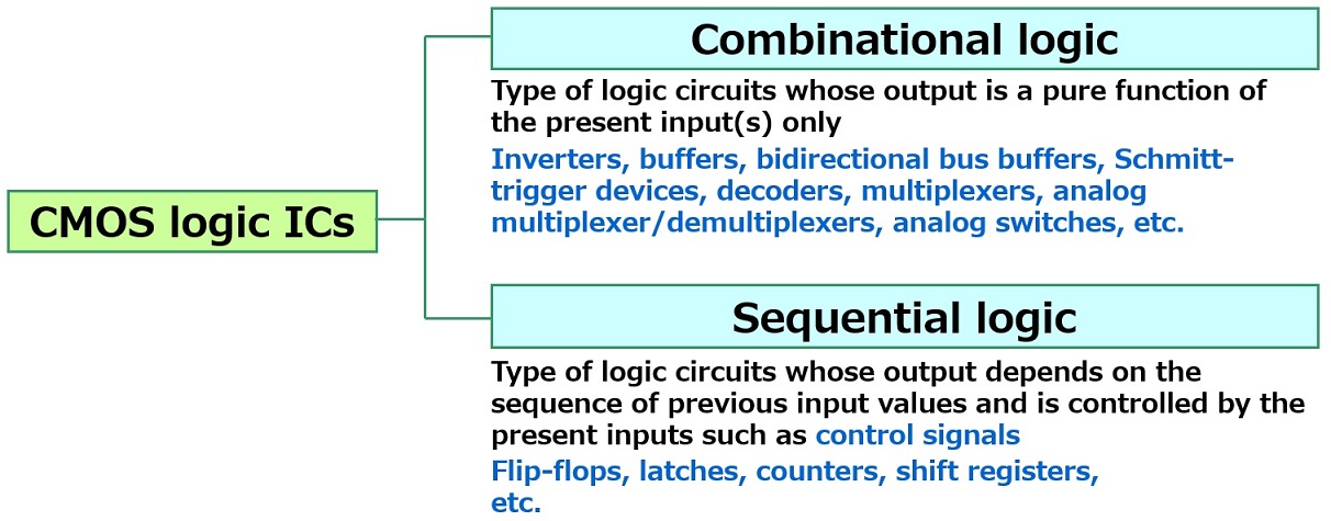
Sequential Logic: Flip-Flops
Flip-flops
Example: 74VHC74
A flip-flop can retain data under specific conditions. The word “flip-flop” is sometimes abbreviated as FF. There are several types of flip-flops such as D-type and JK flip-flops. As an example, the following describes the operation of a D-type flip-flop.
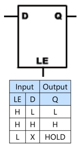
A D-type flip-flop differs from a D-type latch in that the D-type flip-flop retains output data even after the clock is set inactive (Low in this example). (A D-type latch transfers data from the D input to the Q output while the LE input is High.)
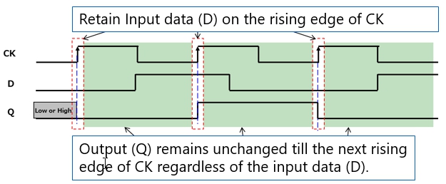
For example, a D-type flip-flop has an input data pin (D), a clock pin (CK), and an output data pin (Q). This flip-flop latches input data (D) on the rising edge of CK and transfers them to Q. Q remains unchanged till the next rising edge of CK regardless of the input data (D). In other words, Q retains the input data (D) latched on the previous rising edge of CK. The following shows the timing diagram of a D-type flip-flop. Some flip-flops have a clear (CLR) or preset (PR) input pin that is used to initialize the internal state to a known value.
Flip-flops are used for synchronizers for asynchronous signals and delay circuits for digital signals as well as counters, frequency dividers, etc.
Operation of a D-type flip-flop
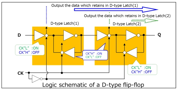
The following describes the operation of a D-type flip-flop using a logic schematic.
A D-type flip-flop consists of two D-type latches.
When a rising clock edge is applied to CK, D-type latch #1 is activated. While the clock (CK) is High, D-type latch #1 remains active, and thus the first clocked inverter in D-type Latch #2 is also active.
Therefore, the data held in D-type latch #1 are transferred to the output (Q) as highlighted by the blue arrow. The output remains unchanged even if the input changes state.
When a falling clock edge is applied to CK, D-type latch #2 is activated.
As a result, the data held in D-type latch #2 continue to appear at the output (Q) as highlighted by the green arrow. Again, the output remains unchanged even if the input changes state.
It should be noted that the value of the output (Q) is unknown until a known input is latched on the rising edge of the clock (CK).

Chapter3 Basic CMOS Logic ICs

Products
Related information
- Application Notes
- FAQ