


- 型號查詢
- 交叉搜尋
- 關鍵字搜尋
- 參數搜尋
- 線上庫存查詢跟購買
This webpage doesn't work with Internet Explorer. Please use the latest version of Google Chrome, Microsoft Edge, Mozilla Firefox or Safari.
型號需要超過三個文字以上
The information presented in this cross reference is based on TOSHIBA's selection criteria and should be treated as a suggestion only. Please carefully review the latest versions of all relevant information on the TOSHIBA products, including without limitation data sheets and validate all operating parameters of the TOSHIBA products to ensure that the suggested TOSHIBA products are truly compatible with your design and application.
Please note that this cross reference is based on TOSHIBA's estimate of compatibility with other manufacturers' products, based on other manufacturers' published data, at the time the data was collected.
TOSHIBA is not responsible for any incorrect or incomplete information. Information is subject to change at any time without notice.
型號需要超過三個文字以上
4 Selection guidelines for TVS diodes (ESD protection diodes)
In order to choose the right ESD protection diode, pay attention to the key electrical characteristics described in Section 3.
1. Maintaining the quality of the signals to be protected
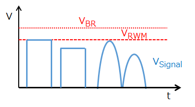
a) Signal line voltage
Select ESD protection diodes with appropriate reverse breakdown voltage (VBR) or working peak reverse voltage (VRWM) according to the maximum voltage of the signal lines to be protected.
b) Signal polarity
Use bidirectional ESD protection diodes for signals that cross the GND level such as analog signals.
c) Signal speed
Select ESD protection diodes with appropriate total capacitance (CT) according to the maximum frequency of the signal lines to be protected.
2. Enhancing ESD protection performance
d) Dynamic resistance
Select ESD protection diodes with dynamic resistance (RDYN) as low as possible.
e) Clamp voltage
Select ESD protection diodes with the minimum clamp voltage (VC) according to the VRWM required.
Be sure to choose diodes with VC lower than the withstand voltage of the device under protection.
3. ESD tolerance of ESD protection diodes
f) IEC 61000-4-2
Select ESD protection diodes with a guaranteed ESD performance higher than a system’s ESD immunity requirement.
Note, however, that the ESD performance of the ESD protection diode is generally proportional to its total capacitance.
g) IEC 61000-4-5
Select ESD protection diodes with electrical ratings higher than the peak pulse power and peak pulse current requirements.
- 1/1
- 1 What is a TVS diode (ESD protection diode)?
- 2 Basic operations of TVS diodes (ESD protection diodes)
- 3 Key electrical characteristics of TVS diodes (ESD protection diodes)
- 5 Layout considerations for TVS diodes (ESD protection diodes)
- 6 Absolute maximum ratings of TVS diodes (ESD protection diodes)
- 7 Electrical characteristics of TVS diodes (ESD protection diodes)
Related information
- Product Web Page
TVS Diodes (ESD protection diodes) - Applidcation Notes
Diode - FAQ
TVS diodes (ESD protection diodes) - Parametric searches for all Toshiba TVS diode (ESD protection diodes) produ cts are available here:
Parametric search - Stock Check & Purchase Toshiba TVS diode (ESD protection diodes) here
Stock Check & Purchase