


3.3. Internal noise of an op-amp
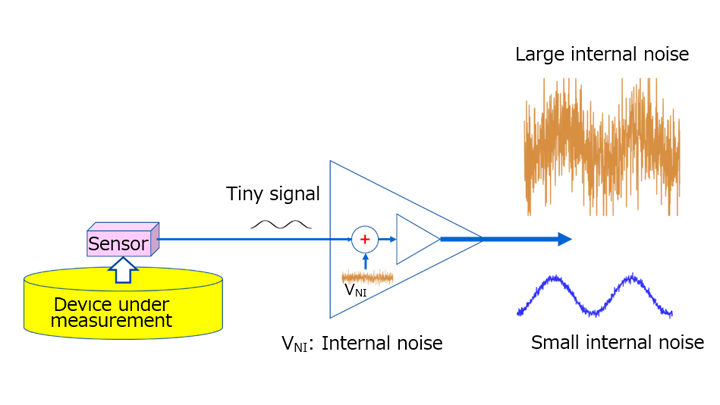
Op-amps are used to amplify a tiny signal from a sensor or other device. Noise is added to this tiny signal and amplified by an op-amp. Therefore, noise contributes to a reduction in the sensitivity and accuracy of a sensor.
The noise related to an op-amp is divided into external noise caused by electromagnetic interference and external parts and internal noise. This section focuses on the internal noise of an op-amp.
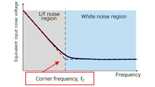
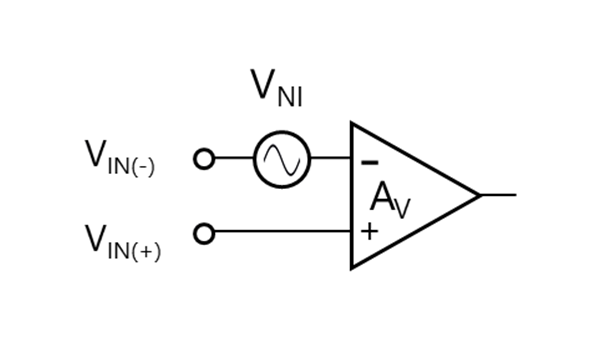
Two types of internal noise are defined as equivalent input noise:
- Frequency-dependent 1/f noise: Thermal noise generated by resistors and shot noise generated by free-moving carriers in a semiconductor
- Frequency-independent white noise: Flicker noise caused by crystal defects and burst noise
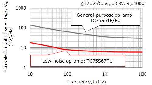
Figure 3-9 shows the noise frequency characteristics of the op-amp, and Figure 3-10 shows an example of the measured equivalent input noise voltage. Figure 3-10 compares Toshiba’s TC75S51 general-purpose op-amp and TC75S67 low-noise op-amp.
The general-purpose op-amp has a white noise of roughly 30 nV/√Hz and a corner frequency of 300 Hz whereas the low-noise op-amp has a white noise of roughly 6 nV/√Hz and a corner frequency of 100 Hz.
Both 1/f noise and white noise appear at the inputs of an op-amp and are defined as equivalent input noise voltage. The equivalent input noise is amplified by a gain and appears at the output. In particular, care is required as to low-frequency noise because its voltage is dependent on frequency.
To amplify a tiny signal, multiple amplifiers are sometimes connected in a cascade in order to prevent abnormal oscillation. Let’s consider how each amplifier stage affects the noise that appears at the output of the cascade amplifier.
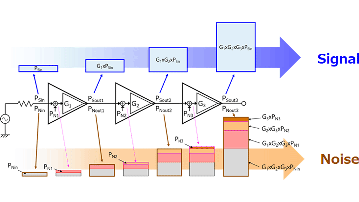
Figure 3-11 shows a three-stage cascade amplifier.
As shown in Figure 3-11, the output signal power (PSout3) and the output noise power (PNout3) can be calculated as follows.
As you see, the input noise (PNin) and the equivalent input noise (PN1) of the first-stage amplifier have the greatest impact on the output noise.
The output signal power (PSout3) and the output noise power (PNout3) are expressed by the following equations:
PSout3 = G1 × G2 × G3 × PSin
PNout3 = G1 × G2 × G3 × (PNin+PN1) + G2 × G3 × PN2 + G3 × PN3
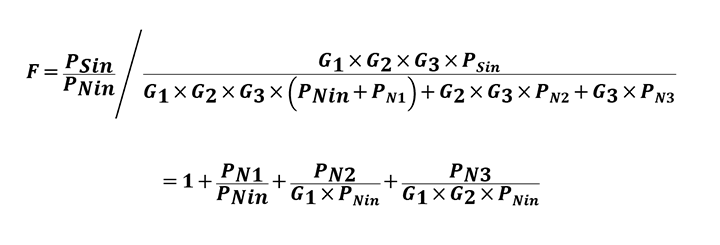
Therefore, the noise factor (F), a measure of noise, is calculated as follows:
The equivalent input noise of the second-stage amplifier (PN2) is divided by the first-stage gain (G1) whereas the equivalent input noise of the third-stage amplifier (PN3) is divided by the first-stage and second-stage gains (G1 and G2). Therefore, the input noise of the successive stages of amplifiers has progressively less impact on the output PNout3.
As indicated by this example, a low-noise amplifier should be used at the first stage to reduce the effect of its noise.
Related information
Chapter3 Electrical characteristics
Related information
- Products
- Application Notes
- FAQs
- Parametric Search
- Stock Check & Purchase