


2.1. Feedback (positive and negative feedback)

Op-amps are generally used with negative feedback.
This section briefly describes negative feedback. There are two types of feedback loops: positive and negative.
For example, positive feedback can be compared to the following cycle:
1) You study hard, and your grades improve.
2) As your grades improve, studying becomes more enjoyable, and you study more.
3) Your grades improve further.
In other words, positive feedback is a process that further increases the effects of a small change in output.
In contrast, negative feedback can be compared to the following cycle:
1) You study hard, and your grades improve.
2) You spend less time studying and more time relaxing.
3) Your grades drop.
4) You spend less time relaxing and more time studying.
5) Your grades get back to the previous level.
It is a process of trying to keep the results (i.e., your grades in this example) constant. This process is called negative feedback.
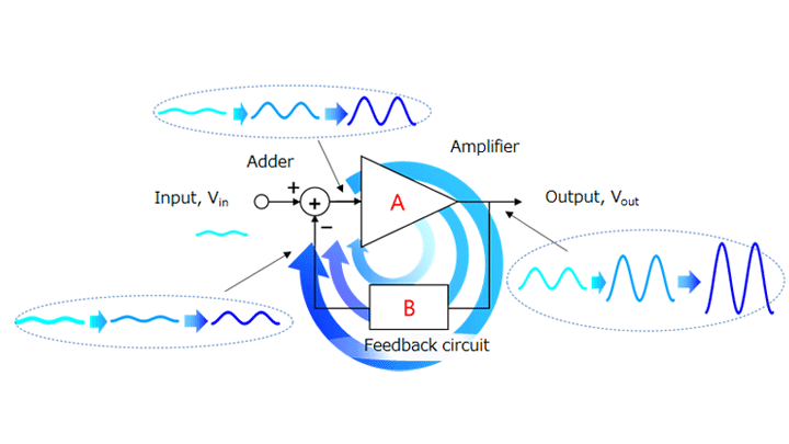
Figure 2-2 shows an amplifier circuit with feedback. It consists of an amplifier, a feedback circuit, and an adder (or a subtractor). AV is the open-loop gain of the amplifier, and B is the feedback factor.
The amplifier amplifies the input signal and outputs an amplified signal. Part of the output is returned to the input of the amplifier via the feedback circuit and the adder.
When Vin changes, negative feedback changes the input to the amplifier in order to counteract the effect of the change in Vin. Conversely, positive feedback increases the effects of the change in Vin.
The output (Vout) is equal to the sum of the Vin and feedback signals multiplied by the open-loop gain of the amplifier:
Vout = AV × (Vin + B × Vout)
This can be rewritten as:
Vout = AV × Vin / (1 − AV × B)
If the feedback signal (AV × B × Vout) has the same phase as the VIN signal, the amplifier circuit has positive feedback. If the feedback signal has the opposite phase to the VIN signal, the amplifier circuit has negative feedback.
Positive feedback: Vout = AV × Vin / (1 − | AV × B |)
Negative feedback: Vout = AV × Vin / (1 + | AV × B |)
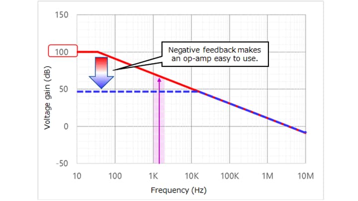
Although an op-amp has a very high open-loop gain, it is difficult to use because of its frequency dependence (see Section 2.2). Therefore, an op-amp is generally used with negative feedback. Negative feedback causes its gain to decrease substantially. On the other hand, negative feedback increases the frequency bandwidth in which the gain curve remains flat and decreases the output impedance. In addition, negative feedback makes it possible to create an easy-to-handle amplifier because it compensates for variations in gain.
Normally, positive feedback is not used for amplifiers. For example, positive feedback is used to provide hysteresis for oscillators and comparators. (If you are interested in this, see the FAQ entry: “How can I provide hysteresis (Schmitt trigger) for a comparator?”
Related information
Chapter2 Using an op-amp
Related information
- Products
- Application Notes
- FAQs
- Parametric Search
- Stock Check & Purchase