


What is eFuse ICs?
Commentary: Overview of eFuse IC "TCKE8xx series"
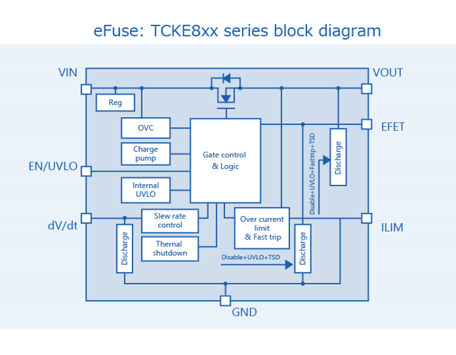
The TCKE8xx eFuse IC series can handle up to 18V / 5A, and have overcurrent protection, short-circuit protection, overvoltage clamp, inrush current reduction, and under voltage lockout (UVLO), thermal shutdown, plus an optional reverse current blocking function. The current limit for overcurrent protection can be set via a single external resistor.
| Features | |
|---|---|
| High input voltage | 18.0 V (max) |
| High output current | 5.0 A (DC) |
| Low ON resistance | 28 mΩ (typ.) |
| Adjustable overcurrent limit protection |
5.0 A (max) |
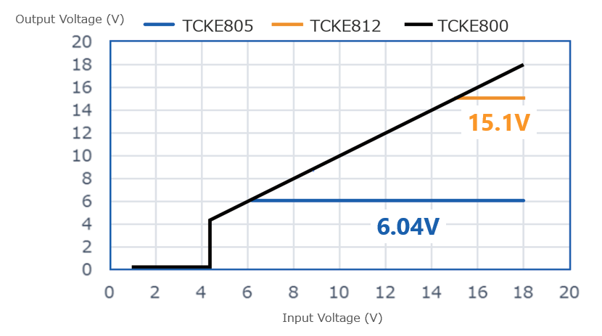
| Built-in fixed overvoltage clamp circuit * Some products do not have overvoltage clamps |
5V power rail=6.04 V (typ.) 12V power rail=15.1 V (typ.) |
|
|
| e Fuse: TCKE8xx series peripheral circuit example |
|---|
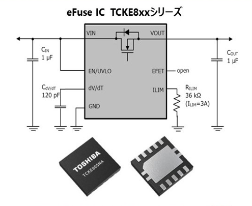 WSON10B(3.0mm × 3.0mm, t: 0.7mm (typ.)) |
| Terminal | Explanation |
|---|---|
| EN/UVLO | This pin has two functions. One function is to enable the output voltage of the internal MOSFET and the EFET terminal. Another function is UVUO function, with adjustable OFF voltage via an external resistor. |
| ILIM | This terminal asjusts the overcurrent limit value. It allows asjustment of the overcurrent limit value with the resistance between the ILIM terminal and the GND terminal. |
| dV/dT | This terminal asjusts the start-up time. The start-up time is adjusted by the capacitance between the dV/dT terminal and the GND terminal. |
| EFET | It is the gate voltage output terminal of the reverse current blocking Nch MOSFET. This should remain open when not using the reverse current blocking function. |
| VIN | Supply input terminal |
| GND | Ground terminal |
| VOUT | Output terminal |
The TCKE8xx series consists of overvoltage clamp voltage and recovery operation type options. The overvoltage clamp voltage is set according to the system voltage to prevent overvoltage from being applied to the load. There are devices with a clamp voltage of 6.04 V (typ) for the 5 V power rail, ones with a 15.1 V (typ) clamp voltage for the 12 V power rail, as well as ones without the overvoltage clamp function.
There are two types of recovery operation. The auto-retry type will automatically try to recover until the failure is resolved, while the latch type is latched during the thermal shutdown operation and is restored by an external control signal to the EN pin once the failure has been resolved.
| Product name | Data sheet | Overvoltage clamp | VEN/UVLO operation |
Recovery operation type | Actual product display | Package |
|---|---|---|---|---|---|---|
| TCKE800NA | PDF(1.6MB) | N/A | Active High | Auto-retry | 800NA |
WSON10B(3.0mm × 3.0mm, t: 0.7mm (typ.)) |
| TCKE800NL | PDF(1.6MB) | N/A | Latched | 800NL | ||
| TCKE805NA | PDF(1.6MB) | 6.04V(typ.) | Auto-retry | 805NA | ||
| TCKE805NL | PDF(1.6MB) | 6.04V(typ.) |
Latched | 805NL | ||
| TCKE812NA | PDF(1.6MB) | 15.1V(typ.) |
Auto-retry | 812NA | ||
| TCKE812NL | PDF(1.6MB) | 15.1V(typ.) |
Latched | 812NL |
What are the features of the eFuse IC?
Commentary: Key TCKE8xx series protection functions
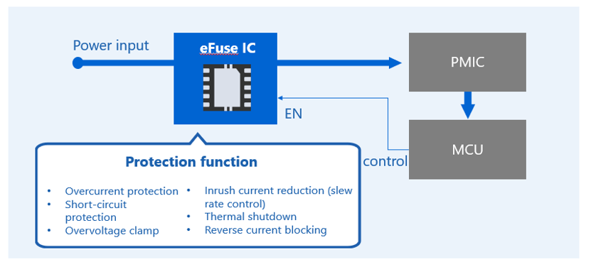
The TCKE8xx series eFuse ICs have the following protection functions. These are intended to safeguard the IC itself and the subsequent stage (load device), in order to reduce the risk of damage. Overcurrent protection, short-circuit protection, and suchlike are functions that detect failure or damage of the load device, preventing smoke, fire, or other forms of damage.
Overcurrent protection function
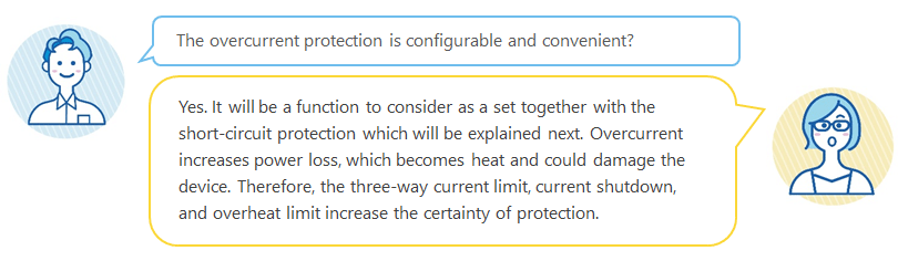
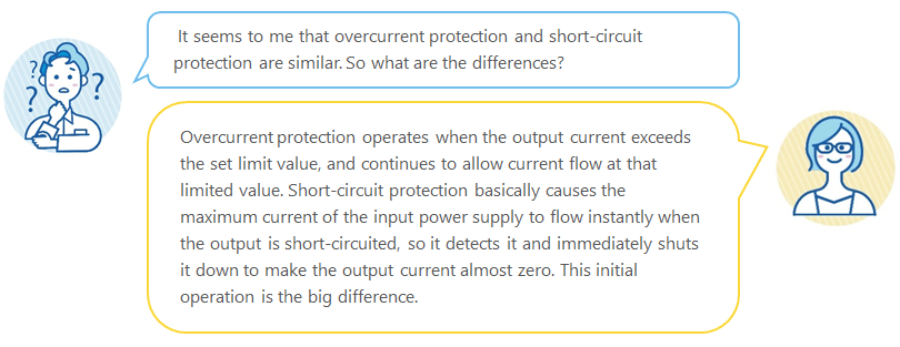
The overcurrent protection function clamps the output current IOUT so that it does not exceed the set limit value when the output current IOUT increases due to an abnormality in the load connected to the VOUT or a short-circuit, preventing momentary interruption of the power supply, while simultaneously protecting against deterioration of the IC itself and the load devices, or damage risks. It also has a short-circuit protection function (described later) that operates when the IOUT substantially exceeds the current limit within a very short time. This means the protection function against overcurrent is double-equipped.
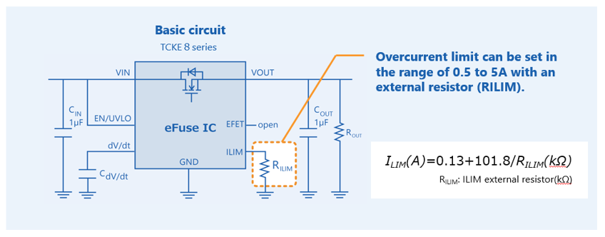
The IOUT limit at which overcurrent protection is activated can be easily set by the external resistor RILIM connected to the ILIM pin. With the TCKE8xx eFuse IC series, this can be set over a wide range of current values, going from 0.5A to 5A. The RILIM value can be set arbitrarily according to the formula, increasing the degrees of freedom for circuit design.
Short-circuit protection function
The short-circuit protection function prevents overcurrent when a load connected to the output VOUT of the TCKE8xx series eFuse IC, or a power supply IC fails and a short-circuit occurs. The eFuse IC determines that a short-circuit occurs when the output current IOUT exceeds 1.6 times the output current limit set by the ILIM pin within a very short time. It immediately turns off the internal MOSFET to shut down VIN and VOUT and suppresses IOUT to almost zero. From the start of overcurrent due to short-circuit to the interruption, the time to shut down is 150 ns (typ.), which is very fast. The shorter the time to shut down, the less damage will be done to the load device. High-speed short-circuit protection characteristics is an important indicator of the performance of electronic fuses. The TCKE8xx series eFuse ICs deliver high-speed performance, due to Toshiba's advanced short-circuit protection technology.

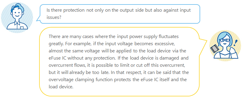
Overvoltage clamp function
The overvoltage clamp is a function that keeps VOUT within the set limit value and prevents the overvoltage from being applied to the load device. The input voltage VIN of the TCKE8 series eFuse IC can be applied up to 18.0V. But some products are equipped with an overvoltage clamp circuit to protect the load device from input overvoltage when used on a 5V / 12V power rail (Not all products). Applicable products clamp the voltage applied to VIN at 6.04V / 15.1V (typ) and output. When the overvoltage clamp function is activated, the power consumption of the eFuse IC generates heat, so the thermal shutdown function works in the same way as overcurrent protection and short circuit protection.
The VIN may be lower than the operating voltage of the eFuse IC, as opposed to the input overvoltage.
In that case, the eFuse IC and subsequent ICs may malfunction, so a low voltage malfunction prevention function (UVLO: Under Voltage Lockout) is also installed. Due to the UVLO function, the TCKE8xx series will not operate unless the VIN is 4.15 V (typ) or higher at startup and will stop operating if the VIN falls below 3.95 V (typ) after startup. The UVLO threshold can be adjusted by attaching an external resistor to the EN/UVLO pin.
Function to suppress inrush current (slew rate control function)
When the MOSFET inside the eFuse IC turns on and the input and output become conductive, the charging current immediately flows to the capacitor at the output. This is called an inrush current, and if it is too large, the overcurrent protection circuit may malfunction - making it impossible to start up or overshooting the output voltage. The function to suppress inrush current controls the rise (slew rate) of the output voltage so as to limit the inrush current to the capacitor, and thereby prevent these inconveniences. In case of the TCKE8xx series eFuse IC, placing an external capacitor at the dV/dT pin will provide the function of controlling the slew rate of the output voltage, so startup can be optimized according to the circuit requirements. The capacitance value of the external capacitor can be easily calculated from the formula described in the datasheet or the graph.
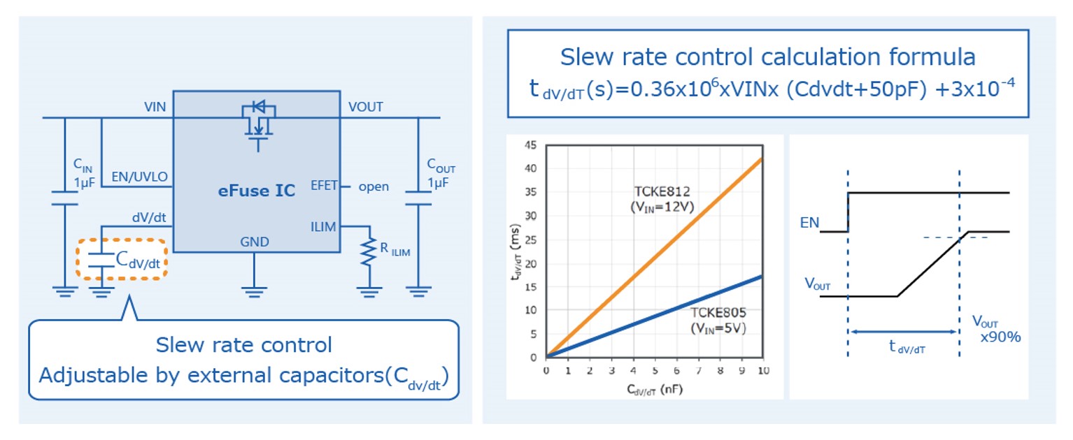
In the waveform at startup, the rising slew rate of VOUT is controlled, with the rise witnessed being gradual, so the charging current to the capacitor at the output also increases gradually, and it can be seen that the inrush current is sufficiently suppressed.

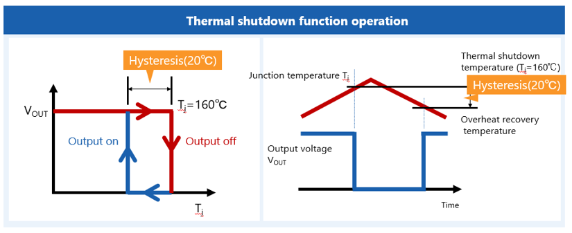
Thermal shutdown function
The thermal shutdown function turns off the built-in MOSFET when the junction temperature (Tj) of the eFuse IC exceeds the set value. This protects the eFuse IC by turning it off to block the output. Toshiba has the product that the interruption lowers the Tj and restores it when it falls below a threshold with hysteresis, and the other type that latches after shutting off. The figure 14 shows an example of the TCKE8xx series.
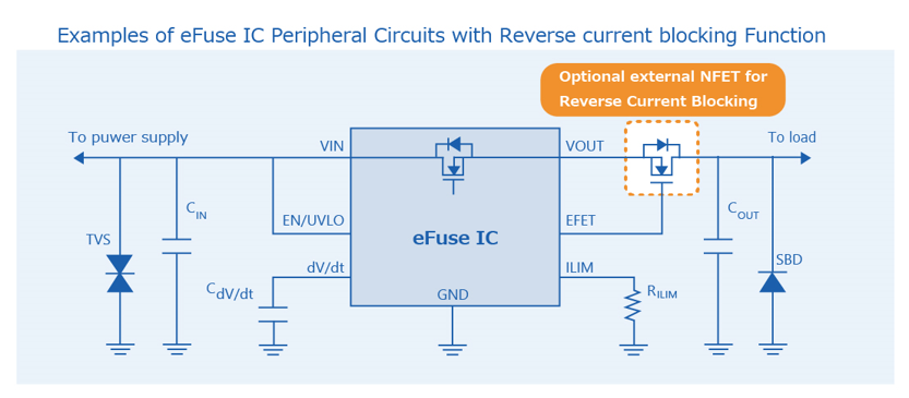
Reverse current blocking function
The reverse current blocking function prevents flowing back the current from the output side to the input side through the parasitic (body) diode of the built-in MOSFET, when the voltage on the output side is higher than that on the input side during the operation of the eFuse IC has stopped (VIN power off, disable state, etc.).
This function is optional and requires one external MOSFET for the TCKE8xx series. EFET pins are provided to control the reverse current blocking MOSFET. So, all you have to do is add the MOSFET to the output line (as shown in the schematic). Please refer to the datasheet for recommended products and specifications for the reverse current blocking MOSFET.
For more detailed information, please see the product page.