


Photocouplers for high-speed communications
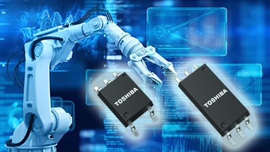
Toshiba Electronic Devices & Storage Corporation (“Toshiba”) has released and begun mass production of four TLP2362B, TLP2368B, TLP2762B, TLP2768B photocouplers for high-speed communications that can operate normally even when the rise time and fall time are slow (slow input below 60 s) at the light-emitting side (primary side) input current and the light-receiving side (secondary side) power supply voltage.
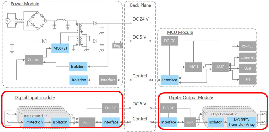
Photocouplers are devices that use electrical insulation as an important function. Light-emitting element and light-receiving element are packaged through light-transmissive insulators. Photocouplers for high-speed communications are ideal for Factory Automation (FA) applications for automation of production processes and for improving and optimizing labor costs and productivity at production sites. Programmable Logic Controllers (PLC) has a particularly important role in FA and are used to control devices and facilities.
PLC is a device that controls efficient machine-to-machine operations by pre-ordering and storing operations that various machines should perform based on "sequential control." They are used in a wide range of fields, including elevators, traffic lights, vending machines, and other familiar facilities, as well as in factory automation facilities and power stations and substations. In particular, when used to control processing and assembly machinery, productivity is significantly improved, contributing greatly to FA at manufacturing sites. Regardless of whether in an enclosure or in a control device, PLC is most often installed in a variety of machines/devices arranged. Therefore, it is necessary to achieve reliable and stable operation in environments where electromagnetic noise and surges are generated by compactness and suppression of heat generation in order to reduce the installation space, as well as operation of peripheral machines and equipment.
PLC is responsible for realizing FA, and the digital input/output modules that support the input and output functions require the external signal line to be isolated from the main unit in signal communication within the module circuitry. We recommend an IC output photocoupler that can be easily and reliably isolated by using an optical coupling photocoupler, enabling high-speed communication. In addition, the international-standard IEC61131-2[Note 1] has begun to be applied. IEC 61131-2 provides test specifications for the behavior of PLC in response to variations in external power. In the gradual shutdown and startup test of the external power supply, it is required to confirm that the power supply shows the predefined behavior at the time of the slow input that the power supply is 60 s turned on and off. The new product complies with this standard, eliminates the need to add components (such as Schmitt trigger circuits) to suppress chattering and contributes to simplification of product design and reduction of external circuits.
Toshiba also has TVS diodes and Zener diodes that are used as peripheral components of photocouplers for high-speed communications.
[Note 1] IEC 61131-2: Industrial Process Measuring and Control-Programmable Controllers-Part 2: Instrument Requirements and Tests
Features
- Slow input on the light-emitting side and slow start of the power supply on the light-receiving side
- High-speed data transmission rate
- High operating temperature rating
1. Slow input on the light-emitting side and slow start of the power supply on the light-receiving side
When the rise time and fall time are slow at the light-emitting side (primary side) input current and the light-receiving side (secondary side) power supply voltage, chattering, which is a phenomenon in which noise is generated in the signal at the output, is a problem.
The new products comply with IEC 61131-2 (Type1). Hysteresis is provided for the threshold of the input forward current and the power supply circuit. Even when the rise time and fall time are slow for the input forward current and the power supply voltage of the light emitting side, the output can be maintained "low" and "high" without chattering. This eliminates the need to add components (such as Schmitt trigger circuits) to suppress chattering and contributes to simplifying design and reducing external circuits.
Figure. 2 shows the behavior of the output voltage (VO) when the input forward current (IF) of TLP2362B is gradually raised from 0 mA to 7.5 mA. Even if IF is set up slowly, TLP2362B does not chatter and maintains a stable VO.
Figure. 3 shows the behavior of the output voltage (VO) when the power supply voltage (VCC) of TLP2362B is gradually raised from 0 V to 2.7 V. Even if VCC is set up slowly, TLP2362B maintains a stable VO. For this reason, the new product does not require the use of components to suppress chattering, such as Schmitt trigger circuits, and contributes to simplification of design and reduction of external circuits.
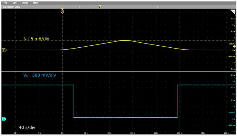
(IF: (Start) 0 to 7.5 mA, (Stop) 7.5 to 0 mA, VCC: 2.7 V, Ta: 25 °C)
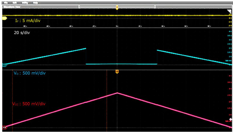
(IF: 7.5 mA, VCC: (Start) 0 to 2.7 V, (Stop) 2.7 to 0 V, Ta: 25 °C)
2. High-speed data transmission rate
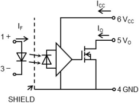
The transmission rates of photocouplers used for communications are limited to a few kbps, but for industrial electronic devices such as PLC, the standby times for data transmission between devices have been shortened, and higher-speed photocouplers are required. As shown in Figure 4, the new products achieve even higher speeds by adding a high-gain, high-speed amplifier circuit to the latter stage of the photodiode. IC coupler with an amplifier has a threshold input current that is digitally turned on/off when the threshold of a LED input current is exceeded. Therefore, analog signals cannot be transmitted linearly and are only used for digital signal transmission.
Typical data-transmission rates enable TLP2362B and TLP2762B to support 10 Mbps, TLP2368B and TLP2768B to support 20 Mbps and help accelerate equipment.
3. High operating temperature rating
The operating temperature is the ambient temperature range within which an element (device) can be operated without impairing the function of the element (device). Temperature is one of the items to be considered in the environmental resistance of PLC. Ambient temperature and other environmental conditions are known to greatly affect the life of PLC, and are generally expected at an ambient temperature of 40 °C. If the operating temperature exceeds the specified range, product malfunction or shorter product life may be disadvantageous. The new product delivers an operating temperature rating (Topr) of 125 °C (max), which helps ensure the safety of the equipment.
Applications
- Factory Automation (FA) control device (programmable logic controller, etc.)
- I/O Modules
- Measuring instruments
Main Specifications
(Unless otherwise specified, Ta=25 °C)
| Part Number | TLP2362B | TLP2368B | TLP2762B | TLP2768B | |||
|---|---|---|---|---|---|---|---|
| Data Sheet | PDF: 842KB |
PDF: 842KB | PDF: 1,486KB | ||||
| Data transmission rate (Mbps) | Typ. | 10 | 20 | 10 | 20 | ||
| Package | Name | 5pin SO6 | SO6L | ||||
| Dimensions (mm) | 3.7×7.0 (typ.), t=2.3 (max) |
3.84×10.0 (typ.), t=2.3 (max) |
|||||
| Absolute Maximum Rating |
Operating temperature Topr (°C) | -40 to 125 | |||||
| Output current IO (mA) | Ta=25 °C | 25 | |||||
| Recommended Operating Conditions |
Supply Voltage VCC (V) | 2.7 to 5.5 | |||||
| Rise time of IF [Note 2] tr(IF) (s) | 5 n to 60 | ||||||
| Fall time of IF [Note 3] tf(IF) (s) | 5 n to 60 | ||||||
| Rise time of VCC [Note 4] tr(VCC) (s) | 10 μ to 60 | ||||||
| Fall time of VCC [Note 5] tf(VCC) (s) | 10 μ to 60 | ||||||
| Electrical Characteristics | Supply current ICCH, ICCL (mA) | Max | 1 | ||||
| Threshold input current (H/L) IFHL (mA) | Max | 5.0 | |||||
| Switching characteristics | Propagation delay time tpHL, tpLH (ns) | Max | 100 | 60 | 100 | 60 | |
| Common-mode transient immunity CMH, CML (kV/ μs) | Ta=25 °C | Min | ±50 | ||||
| Isolation Characteristics | Isolation voltage BVS (Vrms) | Ta=25 °C | Min | 3750 | 5000 | ||
| Sample Check & Availability |  |
|
|
|
|||
[Note 2] Times required to linearly increase the incoming forward current from 0 mA to 7.5 mA.
[Note 3] Times required to linearly reduce the incoming forward current from 7.5 mA to 0 mA.
[Note 4] Times required to linearly increase the supply voltage from 0 V to 2.7 V.
[Note 5] Times required to linearly reduce the supply voltage from 2.7 V to 0 V.
Related information
Application
Queries about purchasing, sampling and IC reliability
Stock Check & Purchase
require 3 characters or more.
* Company names, product names, and service names may be trademarks of their respective companies.