
-
My ToshibaSemicon
- General Top View
-
SEMICONDUCTOR View
-
ApplicationsAutomotive
Body Electronics
xEV
In-Vehicle Infotainment
Advanced Driver-Assistance Systems (ADAS)
Chassis
IndustrialInfrastructure
BEMS/HEMS
Factory Automation
Commercial Equipment
Consumer/PersonalIoT Equipment
Healthcare
Wearable Device
Mobile
Computer Peripherals
-
ProductsPower Semiconductors
SiC Power Devices
*
 : Products list (parametric search)Isolators/Solid State Relays
Photocouplers
Digital Isolators
Solid State Relays
Fiber Optic Transmitting Modules
*
: Products list (parametric search)MOSFETsIntelligent Power ICs*
: Products list (parametric search)IGBTs/IEGTsMotor Driver ICsPower Management ICsBipolar Transistors*
: Products list (parametric search)Linear ICsMicrocontrollersDiodes*
: Products list (parametric search)Automotive DevicesDiscrete Semiconductor
Diodes
Transistors
Logic ICs
Analog Devices
Digital Devices
Wireless Devices
*
: Products list (parametric search)General Purpose Logic ICsICs for Wireless Communication EquipmentInterface Bridge ICs for Mobile Peripheral DevicesRadio-Frequency Devices*
: Products list (parametric search)Sensors*
: Products list (parametric search)Linear Image SensorsOther Product ICs*
: Products list (parametric search) -
Design & Development
-
Knowledge
Knowledge
- Where To Buy View
-
My ToshibaSemicon
-
- STORAGE View
- COMPANY View


- Part Number Search
- Cross Reference Search
- Keyword Search
- Parametric Search
- Stock Check & Purchase
This webpage doesn't work with Internet Explorer. Please use the latest version of Google Chrome, Microsoft Edge, Mozilla Firefox or Safari.
require 3 characters or more.
The information presented in this cross reference is based on TOSHIBA's selection criteria and should be treated as a suggestion only. Please carefully review the latest versions of all relevant information on the TOSHIBA products, including without limitation data sheets and validate all operating parameters of the TOSHIBA products to ensure that the suggested TOSHIBA products are truly compatible with your design and application.Please note that this cross reference is based on TOSHIBA's estimate of compatibility with other manufacturers' products, based on other manufacturers' published data, at the time the data was collected.TOSHIBA is not responsible for any incorrect or incomplete information. Information is subject to change at any time without notice.
require 3 characters or more.
7 Electrical characteristics of TVS diodes (ESD protection diodes)
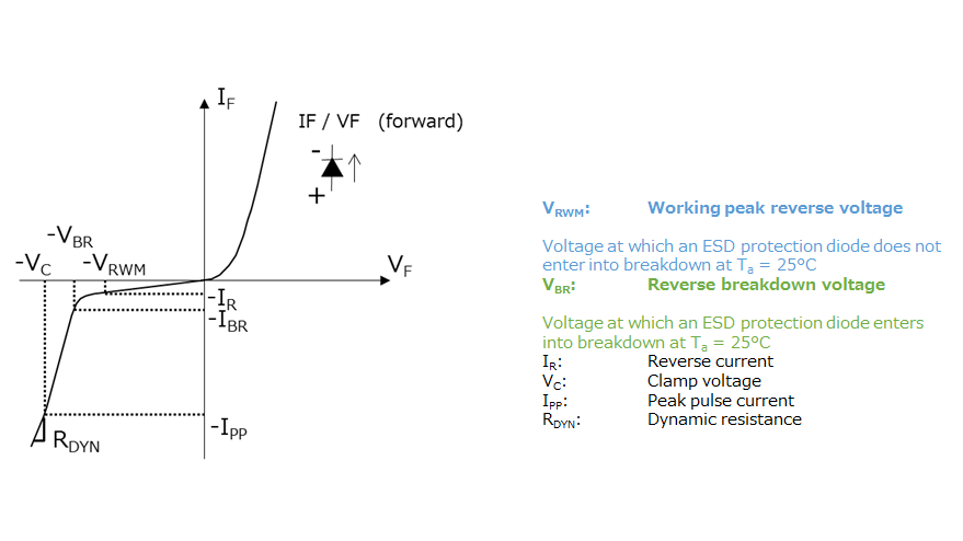
Electrical characteristics
Working peak reverse voltage, VRWM
At a voltage lower than the working peak reverse voltage, an ESD protection diode exhibits a very high impedance. (Even if the working peak reverse voltage is applied, only a current less than the specified leakage current flows.) The designer can use this parameter as a guide to ensure that it is above the maximum operating voltage of the signal line to be protected.
Total capacitance, Ct
CT is the equivalent capacitance across a diode’s terminals when a small signal is applied at the specified reverse voltage and frequency. The total capacitance is the sum of the junction capacitance of a diode and the parasitic capacitance of its package. Junction capacitance decreases as reverse voltage increases.
Dynamic resistance, RDYN
The dynamic resistance is the current slope of the VF–IF curve between VBR and VC when an ESD protection diode goes into reverse breakdown as reverse voltage is increased. The dynamic resistance and the clamp voltage described below represent the ESD performance of an ESD protection diode.
Reverse breakdown voltage, VBR
Reverse breakdown voltage is the voltage at which an ESD protection diode begins to conduct the specified amount of current under specified conditions (defined typically at 1 mA, although this differs from device to device). VBR is originally a parameter defined for Zener diodes. VBR is defined as the voltage at which an ESD protection diode turns on.
Reverse current, IR
Reverse current is the leakage current that flows in the reverse direction when an ESD protection diode is reverse-biased at the specified voltage. In the case of ESD protection diodes, IR is defined at the working peak reverse voltage (VRWM).
Clamp voltage, VC
Clamp voltage is the maximum voltage to which an ESD protection diode is clamped when exposed to the specified peak pulse current. VC is generally measured at multiple peak pulse current points. As shown in Section 6 (Figure 6.1), an 8/20 μs waveform is used for the peak pulse current. The dynamic resistance and the clamp voltage represent the ESD performance of an ESD protection diode.
- 1/1
- 1 What is a TVS diode (ESD protection diode)?
- 2 Basic operations of TVS diodes (ESD protection diodes)
- 3 Key electrical characteristics of TVS diodes (ESD protection diodes)
- 4 Selection guidelines for TVS diodes (ESD protection diodes)
- 5 Layout considerations for TVS diodes (ESD protection diodes)
- 6 Absolute maximum ratings of TVS diodes (ESD protection diodes)
Related information
- Product Web Page
TVS Diodes (ESD protection diodes) - Applidcation Notes
Diode - FAQ
TVS diodes (ESD protection diodes) - Parametric searches for all Toshiba TVS diode (ESD protection diodes) produ cts are available here:
Parametric search - Stock Check & Purchase Toshiba TVS diode (ESD protection diodes) here
Stock Check & Purchase